No products in the cart.
Home Core Science
Electronics – As a base for building Robots
Learn about breadboard, battery, LED, Beeper, switch and circuit diagrams and how to use multimeter, resistor, transistor and relays.
Hello Visitor!
You have not purchased this topic.
Some of the premium content such as Flash Notes, Experiment Videos, Recorded Lecture, Quizzes, etc. is only available after purchase.
Electronics – As a base for building Robots
For Grades 5 - 12 ( Students / Enthusiasts )
Out of stock
Video: Know your components
Breadboard Connections

Recorded Lecture: Working with Breadboard
Premium Content Available, Please purchase to get access.
Circuit Diagram
Recorded Lecture: Circuit Diagram
Premium Content Available, Please purchase to get access.
Refer the color code table above to infer value of a resistor by its color bands and vice versa.
Recorded Lecture: Resistor Color Codes
Premium Content Available, Please purchase to get access.
Recorded Lecture: Circuit Challenge
Premium Content Available, Please purchase to get access.
Build the circuit on breadboard. What happens when you press the switch ?
Circuit diagram referred in the video is given below. (Note: if you don’t have the exact value of resistors then use any resistor where the 3rd band is of the color indicated in the diagram)
Recorded Lecture: Resistance Current
Premium Content Available, Please purchase to get access.
Recorded Lecture: Ohm’s Law
Premium Content Available, Please purchase to get access.
Recorded Lecture: Introducing Multimeter
Premium Content Available, Please purchase to get access.
Circuit diagram referred in the video is given below. (Note: if you don’t have the exact value of resistors then use any resistor where the 3rd band is of the color indicated in the diagram)
Recorded Lecture: Voltage with Multimeter
Premium Content Available, Please purchase to get access.
Circuit diagram referred in the video is given below. (Note: if you don’t have the exact value of resistors then use any resistor where the 3rd band is of the color indicated in the diagram)
Recorded Lecture: Current with Multimeter
Premium Content Available, Please purchase to get access.
Circuit diagram referred in the video is given below. (Note: if you don’t have the exact value of resistors then use any resistor where the 3rd band is of the color indicated in the diagram)
Recorded Lecture: Resistance with Multimeter
Premium Content Available, Please purchase to get access.
Build the circuit and answer the questions below
(Note: if you don’t have the exact value of resistors then use any resistor where the 3rd band is of the color indicated in the diagram)
Q. What value are you using for R1 resistor ?
Q. What value are you using for the two R2 resistors ?
Q. What’s the voltage at point A in the circuit ?
Q. What’s the current flowing through the LED ?
Q. What’s the total effective resistance of the circuit ?
Premium Content Available, Please purchase to get access.
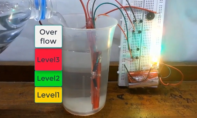
Create a working water overflow alarm model based on the circuit above. Measure the current flowing through the Green LED when its on. Also Measure the resistance of Water in the circuit.
Recorded Lecture: Home Assignment
Premium Content Available, Please purchase to get access.
Q. Why does the circuit have an additional resistor (220 ohm) besides the Potentiometer ?
Q. What’s the maximum resistance value that can give a noticeable glow with your LED ?
Circuit diagram referred in the video is given below. (Note: if you don’t have the exact value of resistors then use any resistor where the 3rd band is of the color indicated in the diagram)
Recorded Lecture: Potentiometer
Premium Content Available, Please purchase to get access.
Circuit diagram referred in the video is given below.
Recorded Lecture: LDR
Premium Content Available, Please purchase to get access.
Recorded Lecture: Introduction to Transistor
Premium Content Available, Please purchase to get access.
Circuit diagram referred in the video is given below. (Note: if you don’t have the exact value of resistors then use any resistor where the 3rd band is of the color indicated in the diagram)
Recorded Lecture: Transistor Circuit
Premium Content Available, Please purchase to get access.
We saw that we can use water as resistor to connect transistor’s base pin to battery positive. How about using your own body ? after all you are 60% water !
Using this idea, can you design and build a working model of a Touch LED circuit, where you can make the LED glow by just your touch ! Demo this circuit in the next session.
Below is a sample demo of such circuit and a tip on building touch sensor.
Recorded Lecture: Home Assignment
Premium Content Available, Please purchase to get access.
For what resistance value, does the mid-point voltage (in controller circuit) become 0.7 V ? (Use potentiometer to find that out)Note: Disconnect the controller circuit from the main circuit (base of transistor) before measuring the mid-point voltage otherwise the transistor will interfere with measurement.
Circuit diagram referred in the video is given below. (Note: if you don’t have the exact value of resistors then use any resistor where the 3rd band is of the color indicated in the diagram)
Recorded Lecture: More on Transistors
Premium Content Available, Please purchase to get access.
Recorded Lecture: Resistance based controllers
Premium Content Available, Please purchase to get access.
What resistance value (for sensitivity control) triggered the beeper at 6am brightness in your simulation? what about 9am brightness ?
Recorded Lecture: Light based controllers
Premium Content Available, Please purchase to get access.
Recorded Lecture: Fine tuning LDR
Premium Content Available, Please purchase to get access.
Circuit Diagram Challenge
We learnt how to fine-tune the improved morning wake-up alarm circuit, so that it triggers at say 6:30am in the morning. Draw the Circuit diagram of the final circuit (with controller and main circuit combined). Also draw circuit diagram of individual circuits (controller circuit and main circuit separately).
Recorded Lecture: Power Supply
Premium Content Available, Please purchase to get access.
Recorded Lecture: Introduction to Relay
Premium Content Available, Please purchase to get access.
Recorded Lecture: Relay Demo
Premium Content Available, Please purchase to get access.
Recorded Lecture: Electrical Side
Premium Content Available, Please purchase to get access.
Recorded Lecture: Pairing with LDR Circuit
Premium Content Available, Please purchase to get access.